Electrical System
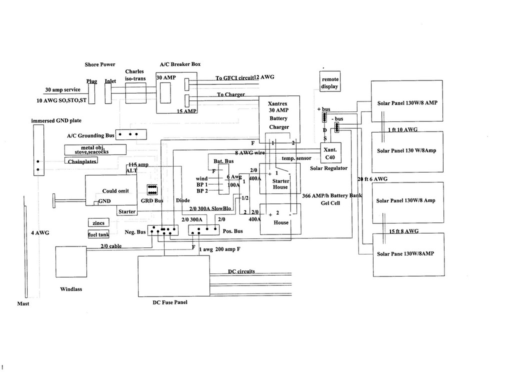
The main electrical diagram for the Rasmus. (above)
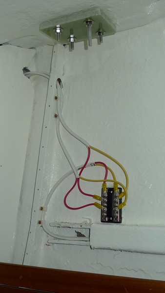
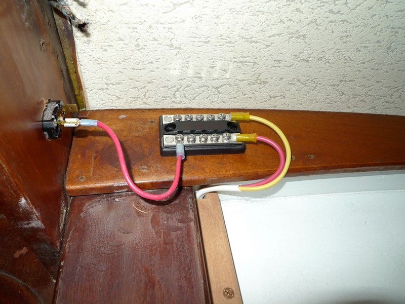
Finished wiring for bow nav. lights. I placed the bus under the slats above the forward settee.
1/28/2010 Continuing the electrical work. Pulled wire for galley lights, head lights, forward berth fan, and mast lights. The Rasmus has plywood and FRP chases running down both sides of the boat which makes a great place to pull wires through. Mounted Xantrex battery charger. Cut the ply panels that will be mounted over the refrigerator that will hold the electrical dc panels. The elec. panels will be mounted on a hinged door for easy access.
Mounting the Brains
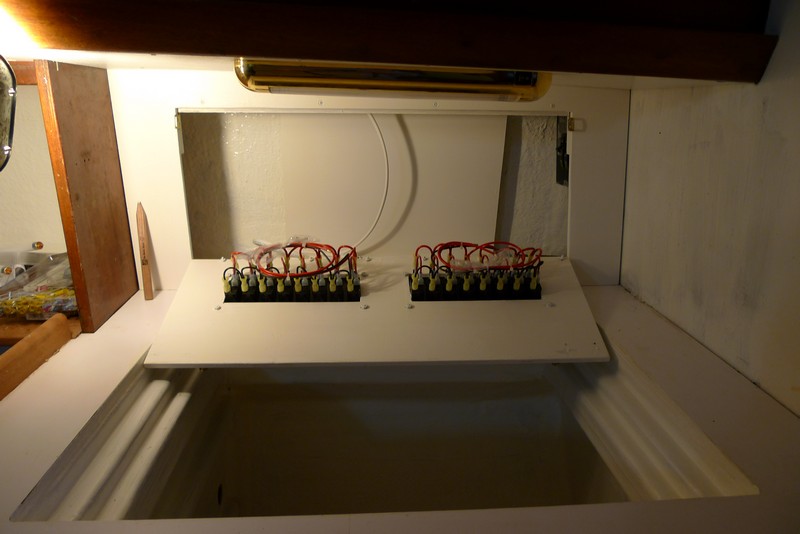
2-18-2010 Today I have installed the "brains" of the Rasmus, two Paneltronics fuse boxes. I used fuses knowing there is less to go wrong with them than with breakers. I placed them over what used to be the navigation station, but is now the refrigerator. The nav. station was a bit too small for me anyway and I will have to provide for navigation somewhere else. I glued a plywood panel on the hull of the boat behind the Paneltronic fuse boxes. I will screw electrical buses and whatever else I need to this. Below are pictures of the days work.
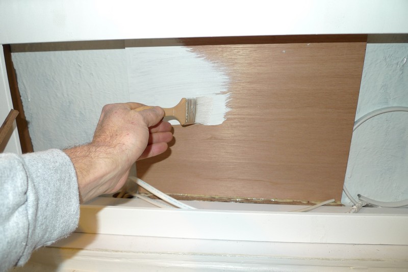
Painting the plywood panel where I will screw on electrical buses
Hinged door drops down so I can service the electrical system
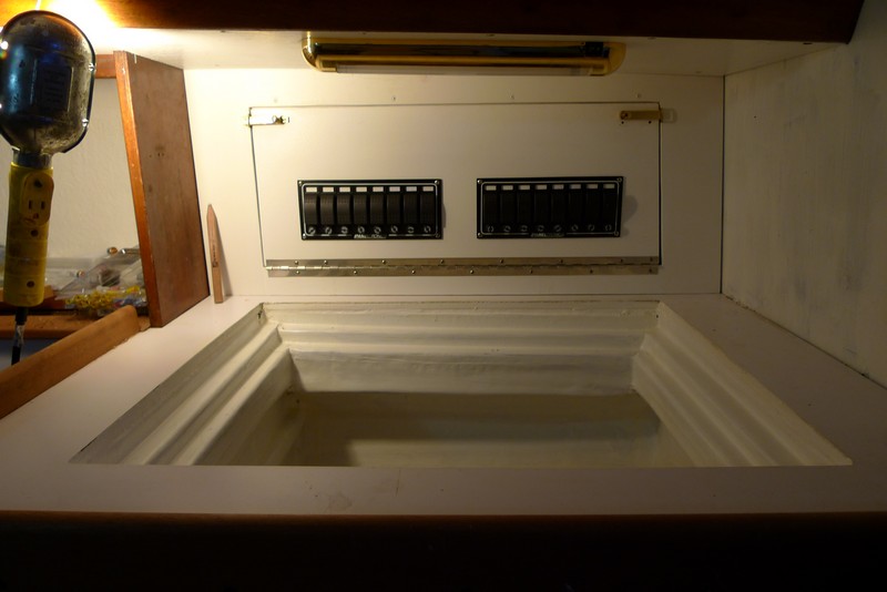
Door in closed postion showing the front to the Paneltronics electrical boxes
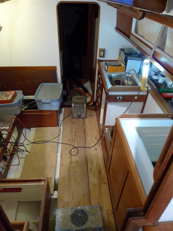
New flourescent lights over sink, stove, and refrigerator. The ceiling panels were originally nailed to the cabin side trim. I opted to screw them back in place to I could more easily service any electrical problems behind them.
More Electrical
I have read and reread Nigel Calder's book "Boatowners Mechanical and Electrical Manual" and have to the best of my abilities laid out an electrical plan for the Rasmus to Nigel's recommendations. I would be amazed if there weren't errors in the system I drew up, but I am sure I will find them out as I go. Below is the "guts" of the system. I hope to get enough courage up to cut the 2/0 battery cable (at $6.00/ft.) with fingers crossed and get on with it this week. Below are diagrams.Click here for lastest electrical schematic
.jpg)
Electrical diagram laid over an image of the Rasmus
.jpg)
Diagram without boat image (above)
Here is a PDF of the new 12V circuits for the Rasmus 12V circuits
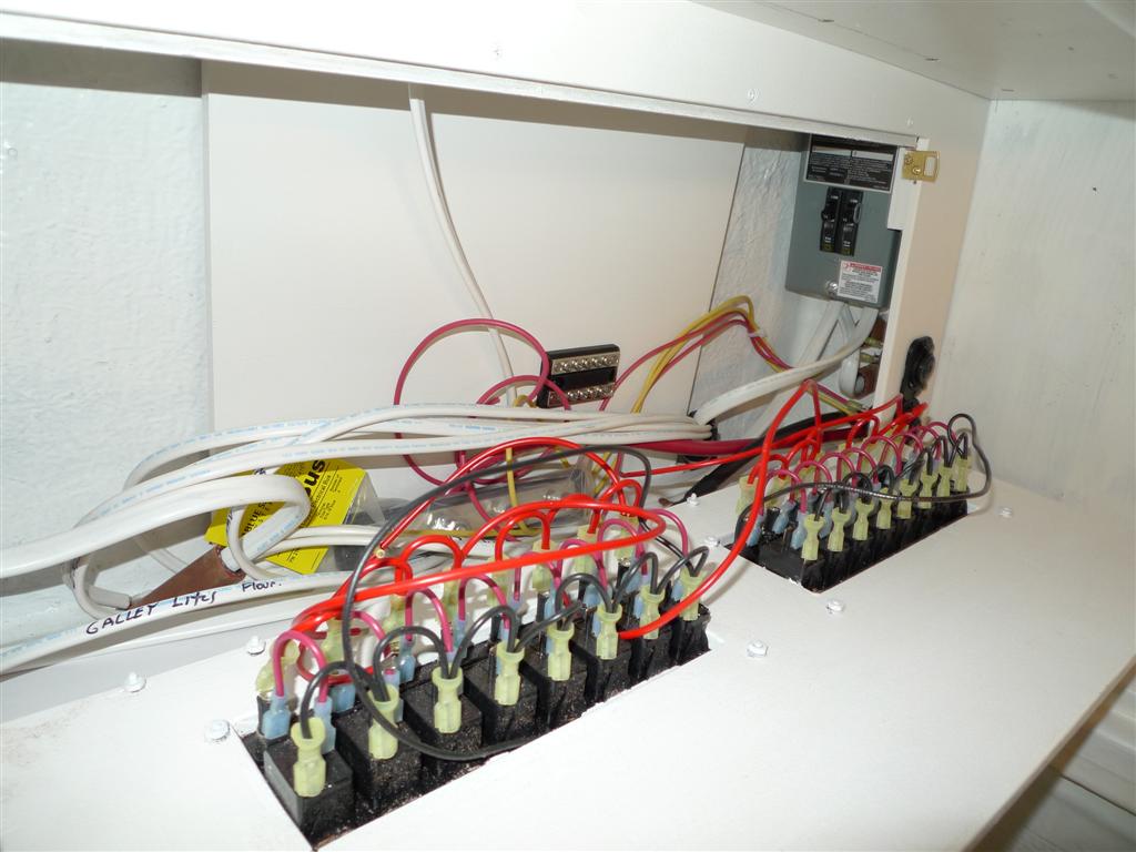
There is a bundle of existing wires coming out of the cabin side within the starboard cockpit locker. Below you can see I have cut them and attached them to a new bus(well, all but two, no idea what these go to). The wires go to the ceiling lites in the hallway in front of the head and main cabin, lites above stove, and mast lites that are bussed at the head entry.
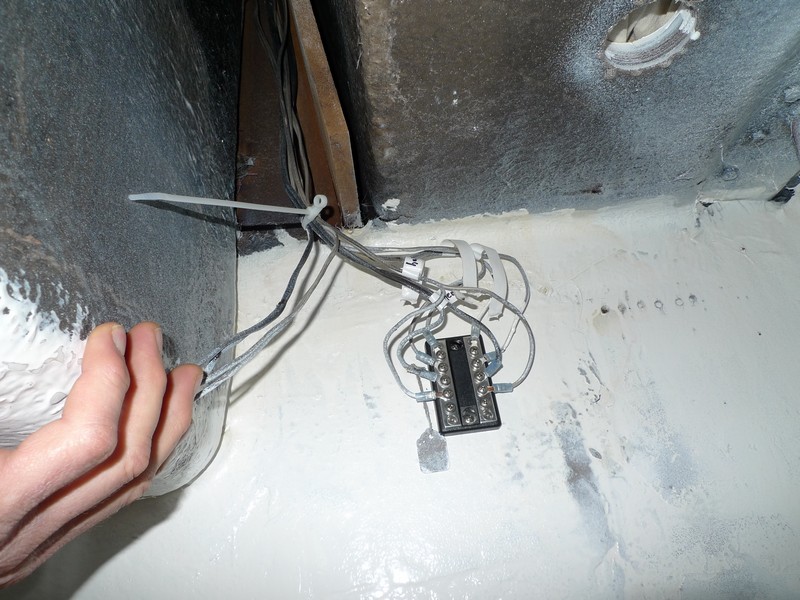
In above photo you can see existing wiring for ceiling lights in main cabin and mast lights. The photo is taken in the starboard cockpit locker. The ceiling lights in main and aft cabin were the only wires I was unable to rewire do to their location.
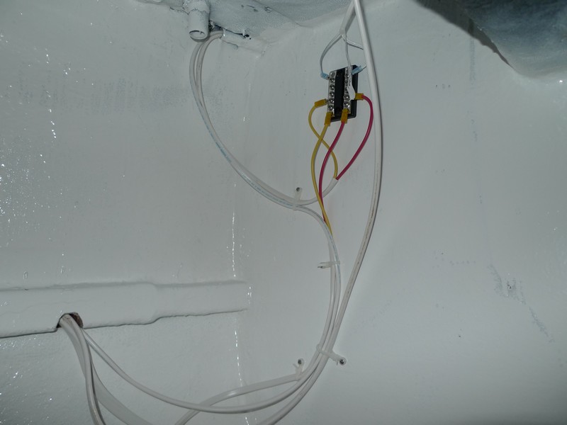
Photo taken in starboard cockpit locker showing wiring for shore power, aft cabin ceiling light, aft cabin fans and added lighting, and stearn navigation lighting (above).
.JPG)
Photo taken in port cockpit locker showing wiring for mast lights, added head locker lights, new main cabin flourescent lighting, and forward berth reading light and fan (above).
I rewired to the mast lights do to bad corrosion on the existing wire. I placed a switch on the mid mast light so I could turn it off and leave the mast head light on in case the glare off the deck was a problem. I had to cut a wooden chase for the new wiring and screw to the head aft bulkhead (above).
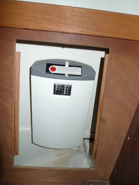
New Zantrex battery charger placed under main cabin settee (above).
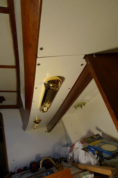
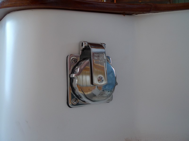
Below is new Marinco Power inlet
More electrical
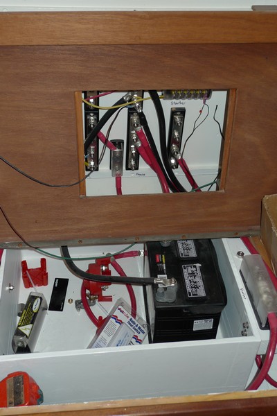
(3-1-2010)Well, I turned 51 today. Life is good! And warmer weather is on the way, thank goodness. It has been a colder than normal winter in Arkansas this year. I wired the 120AC breaker box, ran #10 wire to battery charger and wired it, ran #1 wire from battery box to DC distribution panel, wired two AC outlets, wired two DC lighter sockets, and set up bus bars and preliminary wiring for batteries. I decided to go with two AGM Lifeline 4D batteries that will give me a combined power output of 420Amp/hrs. I am going to wire them as two battery banks and see if 210Amp/hrs is enough to power the boat and use the other as a starter battery. If that does not work out, I will combine the two 4D batteries for the house bank and add a battery for starting. I have wired it so the possible conversion will be easy. Below are pictures of the work.
Most of the wires are pulled to the distribution box. I am waiting on the mailman to bring a bus bar to finish this up
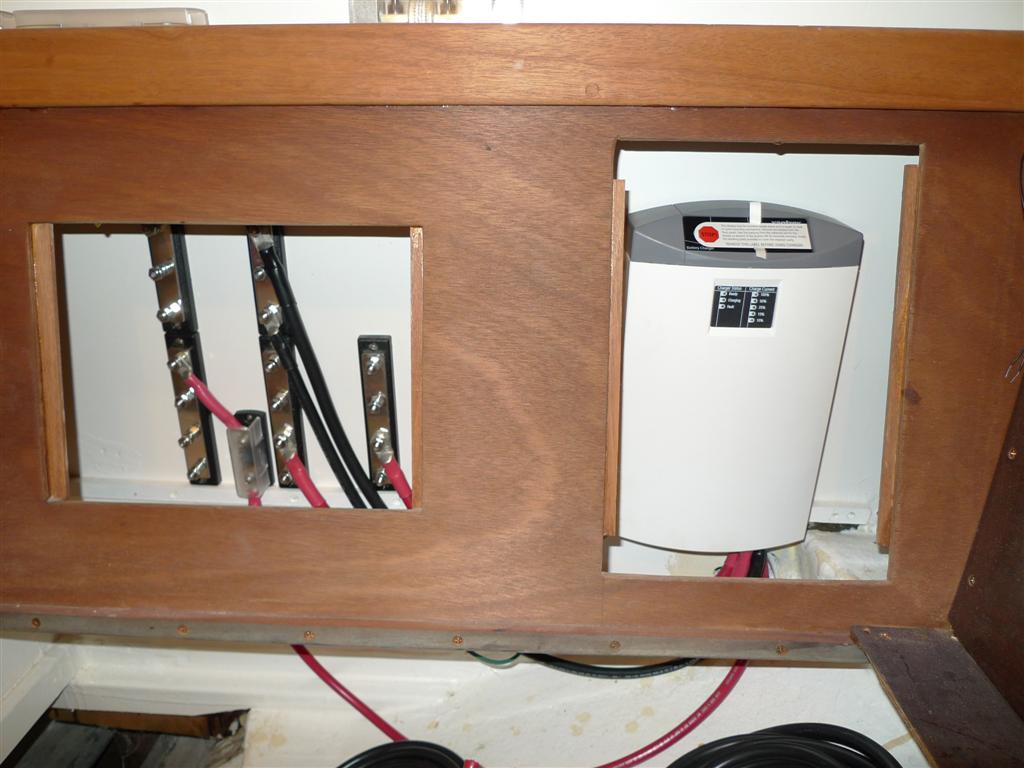
I have started the wiring layout at the battery charger and battery banks. I am waiting on my battery box to dry to finish this up(I made one out of 1/2" plywood and epoxy).
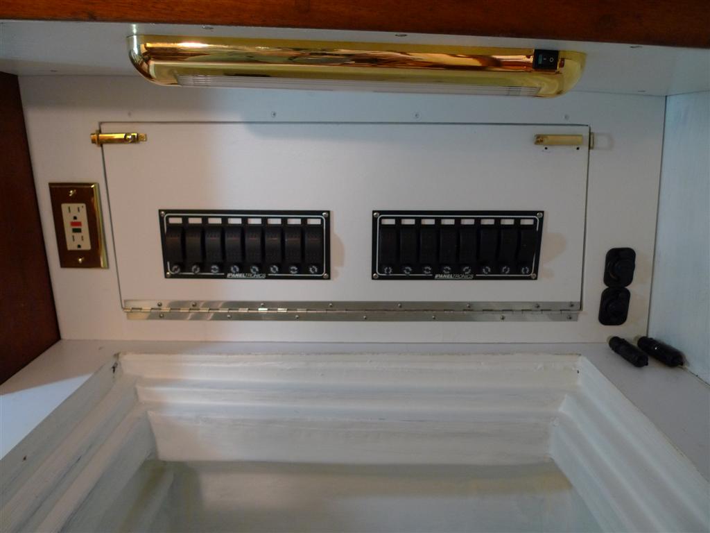
I added a 120V AC outlet and two 12V lighter plugs on front of the panel.
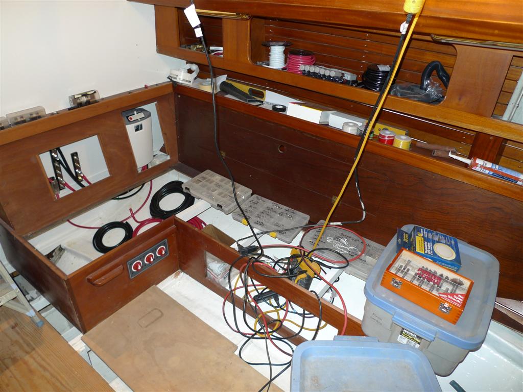
An overall look at the work at this stage (above and below).
Electrical test
Hooked up a battery and turned on the power with fingers crossed and nose on alert. I sensed no wires frying and no breakers popping so all is well.
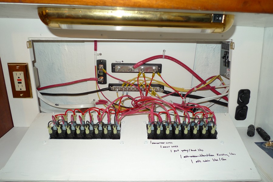
A look at the fully wired electrical panel.